Inner Analysis Report for Industrial Wet Scrubber-A Probe In Wet Dust Collector with Calculation
- Share
- Issue Time
- May 29,2024
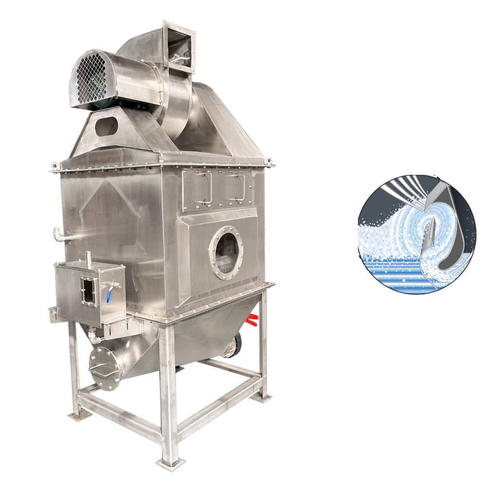
Table 2-1 Comparison between wet dust removal and dry dust removal
|
Wet Dust Collector
|
Dry Dust Collector
|
|
advantage: 1. Can capture gas and dust at the same time 2. Recovered soluble matter can be pumped to another device proceed to the next step 3. It can cool and wash high-temperature gas 4. Can recycle and neutralize corrosive gas and liquid droplets 5. Use water as washing liquid to prevent fire and explosion 6. Less equipment investment, relatively simple structure and small body shortcoming: 1. To consume a certain amount of water (or other liquids), the sewage needs to be treated after dust removal to prevent secondary pollution 2. Dust recovery is difficult 3. Viscous dust is prone to clogging and hanging ash 4. Antifreeze needs to be considered in winter 5. After washing, the exhaust humidity is high and the dew point is low |
advantage: 1. The recovered dry material does not need to be reprocessed 2. Corrosion can be avoided in most cases 3. High-efficiency dust collectors can be produced 4. Radioactive dust can use combustible filter material shortcoming: 1. Hygroscopic substances will cake and be difficult to remove 2. Equipment maintenance and dust disposal will endanger the operation 3. High temperature may limit dust removal methods 4. For some dust collectors (such as filter bag dust collectors), the use of corrosive liquid beads is limited |
Mechanism of wet dust removal
The catch in wet dust removal is water or other liquids. According to its different forms when collecting dust particles: liquid droplets, liquid film, and liquid layer, wet dust removal can be divided into three types accordingly. Among them, the dust removal method using liquid droplets as dust collectors is the most widely used, and it can be subdivided into several types due to the different ways of generating liquid droplets.
1) Droplet wet dust removal
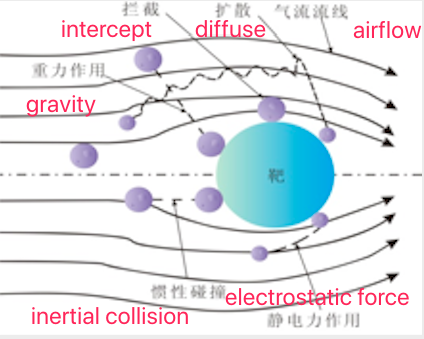
Droplet wet dedusting mainly depends on the full contact between the dust-containing gas and the evenly dispersed droplets in a closed space, and the capture of the droplets on the dust particles is realized through the effects of inertial collision, interception, diffusion, gravity, electrostatic force, etc., such as As shown in Figure 2-1.
The basic inertial collision, interception and diffusion effects will be described below. It is assumed that dust particles are captured as soon as they contact the capture body.
Inertial collision is the most common dust removal effect in wet dust removal. The inertial collision effect only considers the mass of dust particles and not its volume.
As shown in Figure 2-2, there is a droplet in front of the dust-laden airflow, and the streamline of the airflow is deflected in front of the droplet. The deflection of the streamline varies with the air velocity. When the velocity is high, the streamline should be close to the surface of the droplet. The front end deflects around the catcher, and at lower speeds the streamline deflects farther away from the catcher. Because the density of the dust particles in the airflow is much higher than that of the gas, under the action of inertial force, their trajectory deviates from the flow line of the airflow and moves towards the direction close to the trapping body. The farthest trajectory where collective collisions occur is called the limit trajectory. Within the range b shown in the figure, all dust particles with a mass not less than m particles will be trapped due to inertial collision with the capture body.Define the inertial collision factor as: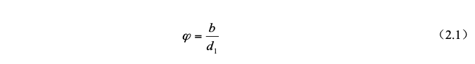
The collision factor φ varies between 0 and 1. The larger the collision factor, the greater the probability of dust being trapped due to inertial collision. The inertial parameter Ψ, also known as the Stokes number, is defined as:
d1—droplet diameter, μm.
In the formula: C—Cunningham sliding correction coefficient
v0—the relative velocity of dust particles and droplets, m/s;
ρp—dust particle density, kg/m3;
dp—diameter of dust particle, μm;
μg—gas dynamic viscosity, Pa s;dl—droplet diameter, μm.
In the formula: C—Cunningham sliding correction coefficient
v0—the relative velocity of dust particles and droplets, m/s;
ρp—dust particle density, kg/m3;
dp—diameter of dust particle, μm;
μg—gas dynamic viscosity, Pa s;
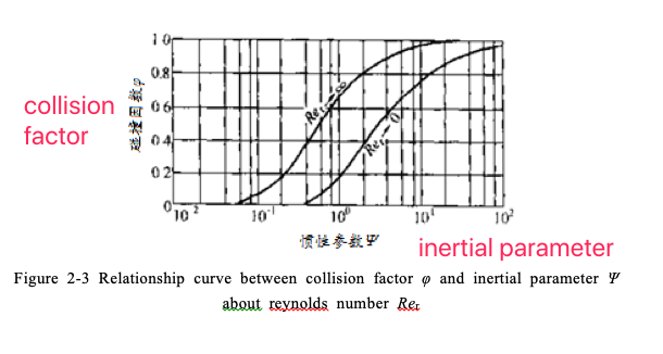
It can be seen from Figure 2-3 that the collision factor φ has a dependence on the inertia parameter Ψ, and the parameter Rer is the Reynolds number.
In the above definition, ρg is the gas density, kg/m3.
Therefore, with the increase of relative velocity v0 between dust particles and liquid droplets, dust particle density ρp, and dust particle diameter dp, due to the effect of inertia, the collision factor will increase, and the probability of dust being trapped will increase; and when the gas viscosity When the μg droplet diameter dl increases, the collision force and friction force dominate, and the dust will bypass the droplet without being trapped.
For a single droplet, the inertial collision trapping efficiency is defined as the percentage of the number of dust particles that have inertial collision with the droplet to the initial number of dust particles in the dusty airflow passing around the droplet. Many scholars at home and abroad have studied the collection efficiency of single droplet inertial collision.
Wong and Johnstone, for the condition of potential flow and inertial parameter Ψ>0.2, proposed a single droplet inertial collision trapping efficiency as:It can be seen from Figure 2-3 that the collision factor φ has a dependence on the inertia parameter Ψ, and the parameter Rer is the Reynolds number.
In the above definition, ρg is the gas density, kg/m3.
Therefore, with the increase of relative velocity v0 between dust particles and liquid droplets, dust particle density ρp, and dust particle diameter dp, due to the effect of inertia, the collision factor will increase, and the probability of dust being trapped will increase; and when the gas viscosity When the μg droplet diameter dl increases, the collision force and friction force dominate, and the dust will bypass the droplet without being trapped.
For a single droplet, the inertial collision trapping efficiency is defined as the percentage of the number of dust particles that have inertial collision with the droplet to the initial number of dust particles in the dusty airflow passing around the droplet. Many scholars at home and abroad have studied the collection efficiency of single droplet inertial collision.
Wong and Johnstone, for the condition of potential flow and inertial parameter Ψ>0.2, proposed a single droplet inertial collision trapping efficiency as:
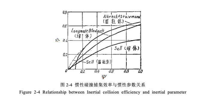
Sell.W et al. conducted experiments to study the longitudinal sections of water streamlines passing through objects of different shapes (the diameters of balls, columns and flat plates are all 10cm), and obtained the relationship curve between the inertial collision capture efficiency ηp and the inertial parameter Ψ as shown in Figure 2-4 Show.
(2)to intercept
Contrary to the inertial impact effect, the interception effect only considers the volume of dust particles, but ignores their mass. Since there is no inertial force without mass, particles of different sizes flow around the trapping body along the streamline. If the minimum distance between the streamline where the particle is located and the surface of the trapping body is less than or equal to the particle radius, the particle will come into contact with the trapping body. And being captured, this is the interception effect.
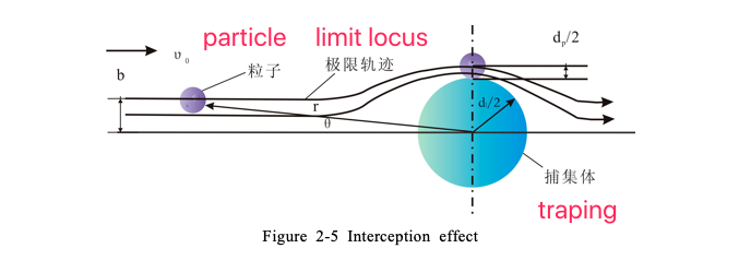
As shown in Figure 2-5, at a position b away from the horizontal centerline of the trapping body, a particle approaches the trapping body along the airflow streamline at a velocity v0. Before approaching the trapping body, the airflow streamline deflects, because the mass of the particle , so the particles are also deflected by the streamline around the capture body. If the shortest distance between the streamline and the surface of the capture body is dp/2, the particles shown in the figure just come into contact with the capture body and are trapped. The trajectory of the particle That is, the limit trajectory of particles of the same size. Within the range of b, particles with a diameter not smaller than dp will contact with the trapping body and be trapped.
The dimensionless interception factor characterizing the interception is defined asAs shown in Figure 2-5, at a position b away from the horizontal centerline of the trapping body, a particle approaches the trapping body along the airflow streamline at a velocity v0. Before approaching the trapping body, the airflow streamline deflects, because the mass of the particle , so the particles are also deflected by the streamline around the capture body. If the shortest distance between the streamline and the surface of the capture body is dp/2, the particles shown in the figure just come into contact with the capture body and are trapped. The trajectory of the particle That is, the limit trajectory of particles of the same size. Within the range of b, particles with a diameter not smaller than dp will contact with the trapping body and be trapped.
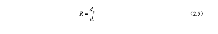
The dimensionless interception factor characterizing the interception is defined as:
The interception efficiency of a single droplet is:
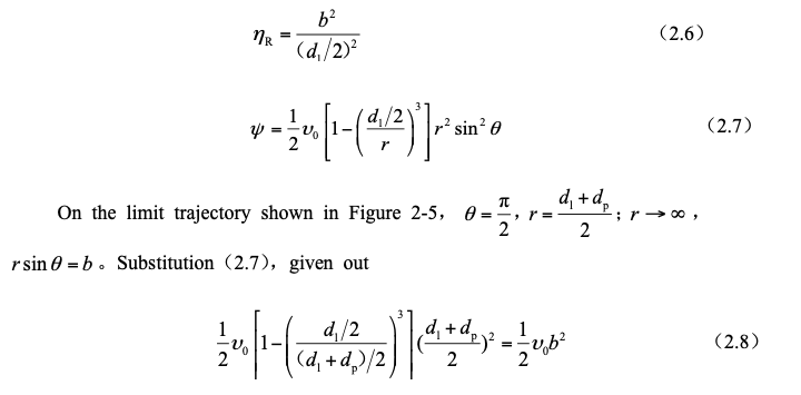
For viscous flow around a sphere at rest, the flow function is:
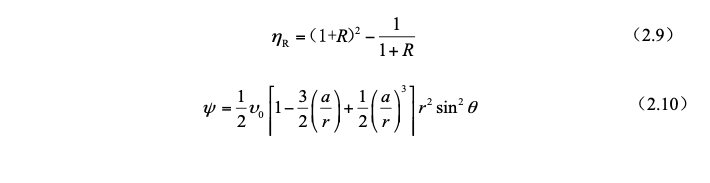
According to the above steps, the interception efficiency of a single spherical droplet is obtained as:
The calculation formula of interception efficiency obtained above can be simplified as follows for viscous flow around a sphere at rest, the flow function is:
According to the above steps, the interception efficiency of a single spherical droplet is obtained as:
The calculation formula of interception efficiency obtained above can be simplified as follows:
The Reynolds number of the droplet flow is defined as:

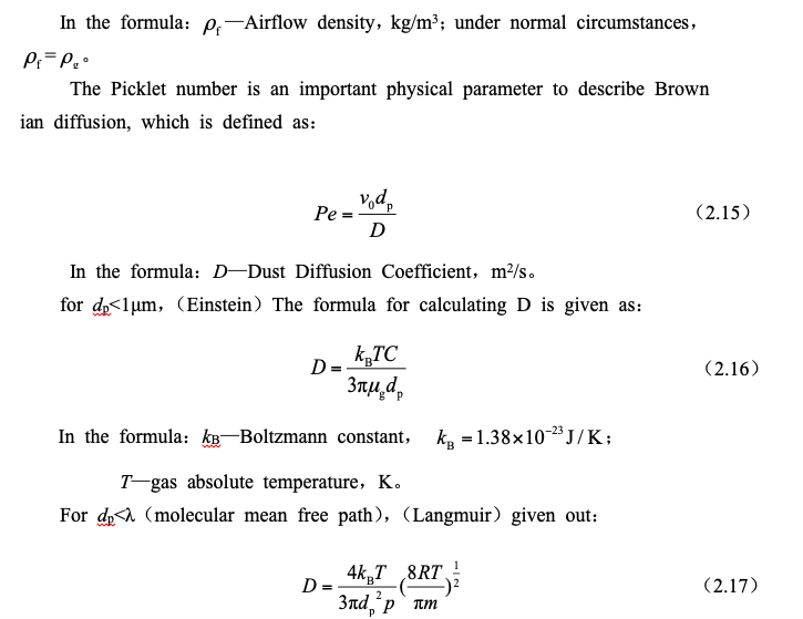
In the formula:R—gas constant,J/(kg·K);
m—gas molar mass,kg;
p—gas pressure,Pa。
Johnstone and RobertsThe diffusion and sedimentation efficiency of a single droplet proposed in 1949 is:

In the actual wet dust removal process, the inertial collision, interception and diffusion effects exist at the same time, and the three mechanisms interact and work together. At this time, the dust removal efficiency cannot be directly obtained through the theoretical calculation formula.
Wet Scrubber Overview
The self-initated dust collector relies on the dust-laden airflow hitting the liquid film or the free liquid surface to form a large number of droplets or water curtains to capture dust particles. The diameter of the droplets produced by this dust collector is small, and the relative velocity between the droplets and the airflow is relatively large, so it has a high dust removal efficiency.
The self-initated dust collector on the driving face as shown in Figure 2-10. After the dust-laden air enters the air inlet chamber I, it hits the free liquid surface, and larger dust particles fall into the water due to inertia during this process. The dust-laden airflow and the aroused water droplets are fully mixed in the curved channel II, and the droplets trap dust particles through inertial collision, interception and diffusion. The purified gas is dehydrated by the dehydrator and then discharged from the dust collector.
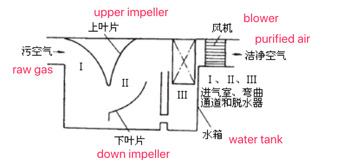
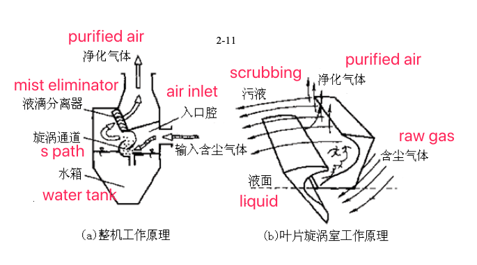
Figure 2-11 is a vortex self-initated wet dust collector. The dust-laden gas and the aroused liquid droplets are fully mixed in the vortex channel to complete the purification work.
Dust removal mechanism of self-initated water curtain and influencing factors of dust removal efficiency
The dust removal process of the self-initated water curtain dust collector is as follows:
The induced draft fan provides power for the whole system, so that a negative pressure environment is formed at the air inlet, and the outside dust-laden airflow is sucked into the air inlet chamber of the dust collector. Under the action of the throttle baffle, the flow area of the dust-laden airflow is rapidly reduced. The speed is small, so the speed is getting bigger and bigger, and reaches the maximum when it flows through the end of the throttle baffle, where the high-speed airflow forms a strong impact on the liquid surface, and the larger particles of dust fall directly into the water due to inertia. The rest of the dust continues to enter the mixing chamber composed of the throttle baffle and the deflector with the airflow. The liquid surface at the end of the throttle baffle is strongly impacted by the airflow and separates a large number of droplets. It sprays into the mixing chamber at a high speed and performs a similar parabolic motion. A large number of droplets complete this action without interruption, forming a water curtain with a certain shape in the mixing chamber, and the droplets are dispersed in the entire airflow. Dust particles are collected comprehensively and efficiently, and the purified airflow entrains a large number of small droplets. When passing through the water barrier, due to the sharp change of the airflow direction, the droplets are separated from the air flow line and collected by the water barrier. Finally The purified air is discharged through the outlet of the induced draft fan.
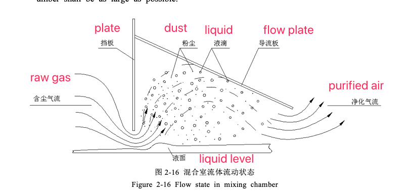
The mixing of dust-laden airflow and liquid droplets in the mixing chamber is the most important stage in the whole dust removal process, which plays a decisive role in the dust removal efficiency of the dust collector. Figure 2-16 is a schematic diagram of the fluid flow state in the mixing chamber.
In the mixing chamber, the trapping body mainly exists in the form of water droplets, and the dust removal mechanism at this time mainly considers inertial collision and interception. From the formula and relationship curve given in 2.1, it can be seen that under the condition of a certain dust density, the dust removal efficiency of a single water droplet is inversely proportional to the diameter of the water droplet, and proportional to the diameter of the dust particle and the relative speed between the dust particle and the water droplet, while for For the whole dust removal system, firstly, the dust removal efficiency of individual water droplets should be improved, and secondly, the number of water droplets in the mixing chamber should be increased, so that the overall dust removal efficiency of the dust collector can be improved. On the other hand, in order to improve the dust removal efficiency of the whole dust removal system, one must increase the relative velocity between the dust particles and the liquid droplets, and second, the diameter of the water droplets forming the water curtain in the mixing chamber shall be as small as possible and the number shall be as large as possible.
and the air volume of the dust collector is jointly determined by the induced fan and the dust removal device. As the load of the induced draft fan, the dust removal device can only be changed by adjusting the throttling baffle or valve. For the induced draft fan (determined by model) equipped with the dust removal device, the control can only be controlled by changing the operating frequency. The higher the operating frequency of the induced draft fan, the greater the processing air volume and the greater the initial inertia of the airflow, and vice versa. The change of the height of the throttle baffle directly affects how much the pressure energy of the airflow can be converted into kinetic energy. The more obvious the throttling effect is, that is, the lower the height of the throttle baffle, the greater the inertial increase of the airflow. On the contrary, the higher the height, the greater the inertial increase. The smaller the amount.
The relationship curve between the operating frequency of the induced draft fan and the dust removal efficiency is shown in Figure 2-17.
The curve in Figure 2-17 is drawn from the data obtained by adjusting the operating frequency of the induced draft fan sequentially under the same self-initated water curtain dust collector test model at different throttle baffle heights. It can be seen from the figure that the dust removal efficiency With the increase of the operating frequency of the induced draft fan, there is a trend of increasing first and then stabilizing.
Taking the h=50mm curve as an example, when the fan runs between 25~45Hz, the dust removal efficiency increases with the increase of frequency, and the change is most obvious before 35Hz; when the fan is running at 45~50Hz, the dust removal efficiency tends to be stable. At 25Hz, because the initial inertia obtained by the airflow is too small, the energy transferred to the liquid surface is too small when it hits the liquid surface, so that sufficient water droplets cannot be aroused, so the airflow bypasses the throttle baffle and enters the mixing chamber. The dust particles cannot be captured in large quantities, and the dust removal efficiency is not high; as the operating frequency of the fan increases, before 40Hz, the initial inertia obtained by the airflow entering the dust collector increases accordingly, and at the end of the throttling baffle The energy transmitted to the liquid surface increases when the liquid surface is impacted, and more and more water droplets break free from the shackles of the liquid surface and enter the mixing chamber with the airflow, and the diameter of the water droplets is also getting smaller and smaller, and the initial inertia of the airflow The increase in itself directly leads to the increase of dust particles falling into the water due to inertia during the process of circumventing the throttling baffle. In addition, it increases the number of water droplets in the mixing chamber and reduces the particle size. In the mixing chamber due to The dust particles captured by inertial collision and interception will also increase accordingly, and the dust removal efficiency will inevitably increase significantly; when the frequency continues to increase to 45Hz, at this stage, when the airflow hits the liquid surface, it will fall into the water due to the inertial effect The dust particles in the airflow continue to increase, although the number of water droplets in the mixing chamber continues to increase with the increase of the frequency, the particle size continues to decrease, and the condition of the water curtain is getting better and better, but because the dust particles in the air flow decrease with the particle size, the trapping The difficulty of collection increases obviously, and the increase of dust removal efficiency in the mixing chamber becomes insignificant, which leads to the slowdown of the increase of dust removal efficiency of the whole dust collector. The dust particles entering the water still continue to increase, and the excessive impulse energy makes the diameter of the water droplets that are partly separated from the liquid surface too small, so that after the dust is captured, they cannot freely settle into the water or be removed by the water barrier, but are separated by the airflow. It is discharged from the outlet of the dust collector, and the originally collected dust particles are released into the environment again, so the dust removal efficiency of the dust collector will no longer increase.
h=30mm In the curve, when the frequency is 25~35Hz, the dust removal efficiency increases with the increase of the frequency; 35~45Hz, the dust removal efficiency is basically stable at the highest value; while 45~50Hz, the dust removal efficiency has a slow downward trend.
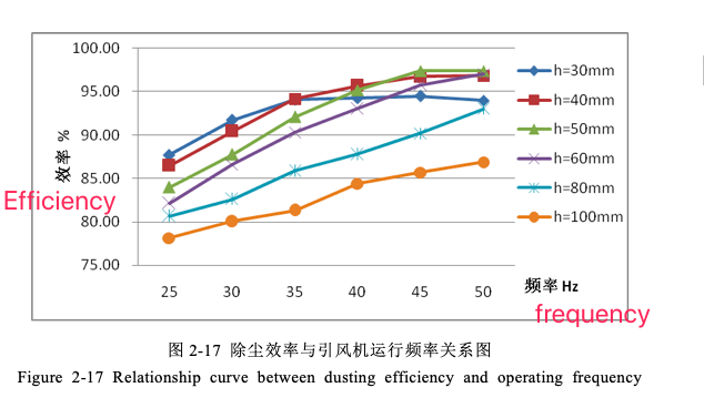
The change trend of the first two stages is the same as the change of the h=50mm curve, and the reason is the same, so I won’t go into details here. At the stage of 45~50Hz, with the increase of the initial inertia of the airflow, although the number of particles falling into the water due to the inertial effect when the airflow hits the liquid surface increases, the excessive impulse energy makes the diameter of the excited water droplets too small, and the fog If the pollution is serious, there will be more and more small droplets carrying the collected dust particles through the water barrier to the outlet of the dust collector with the airflow. Because of this, the dust removal efficiency will slowly decline.
For the two curves h=80mm and h=100mm in the figure, in the frequency range of 25~50Hz, the dust removal efficiency has been increasing with the increase of frequency, and there is no stable section in the h=50mm curve, which is Because the height of the throttle baffle is too high at this time, the inertia increment obtained by the dust-laden airflow passing through the throttle baffle is not large. Even if the induced draft fan operates at a high frequency, the water curtain in the mixing chamber cannot be fully spread. The state, so it can not reach the highest dust removal efficiency. Obviously, if we can continue to increase the processing air volume of the dust collector at this time, so that the initial inertia of the dusty airflow continues to increase, the maximum dust removal efficiency at this baffle height will be reached like other curves.
The relationship curve between throttle baffle height and dust removal efficiency is shown in Figure 2-18
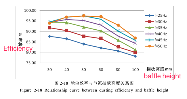
As mentioned above, the height of the throttle baffle directly affects the size of the inertial increment after the airflow passes through the baffle. The smaller the size, the less water droplets will leave the liquid surface, and the larger the particle size, the worse the condition of the water curtain in the mixing chamber, and the lower the dust removal efficiency; on the contrary, the lower the baffle height, the greater the energy obtained by the liquid surface. The better the condition of the water curtain in the mixing chamber, the higher the dust removal efficiency; however, if the height of the baffle is too low, the particle size of the water droplets will be too small, and the dust will be discharged from the outlet with the airflow bypassing the water barrier, thereby reducing the dust removal efficiency. . Therefore, there must be an optimal throttle baffle height hm, so that the dust removal efficiency of the dust collector at a certain frequency can reach the highest.
Take the f=50Hz curve in Figure 2-18 as an example, the curve as a whole shows a trend of rising first and then falling, and reaches the maximum value at h=50mm, that is to say, when the operating frequency of the induced draft fan is 50Hz, the optimal throttle gear Board height hm=50mm. At this time, reducing the height of the baffle will lead to severe water discharge at the outlet of the dust collector, and the dust removal efficiency will decrease; if the height of the baffle is increased, the inertia increment will decrease after the airflow bypasses the baffle, and the condition of the water curtain in the mixing chamber will deteriorate, reducing the dust removal efficiency. For the two cases of frequency f=25 and 30Hz, there is only a descending section in Fig. 2-18. This is because the initial inertia of the airflow in these two cases is too small, so under this test condition, there is no water droplet size that is too small. In the case of severe water discharge at the outlet, the hm at these two frequencies should be less than or equal to 30mm.
The aroused water droplets break away from the air flow line in the mixing chamber and collide with the water film formed on the deflector, which also has a trapping effect on the dust particles. The capture effect of water film on dust is very complex, and its capture efficiency is related to factors such as dust particle size, dust concentration, wettability of dust, and stability of water film.
The larger the particle size of the dust, the greater the degree of separation from the streamline when the airflow encounters the deflector and the deflection of the streamline, so the greater the probability of hitting the water film and being captured. In addition, the dust is captured by the liquid film. In fact, the gas-solid interface on the outer wall of the dust particle is replaced by the liquid-solid interface, and the dust particle breaking through the outer gas film is the prerequisite for this replacement. The particles are not easy to break through because they are tightly wrapped by the air film, and it is difficult to be captured by the water film.
Excessive dust particle concentration will reduce the dust removal efficiency of the water film. Excessive particle concentration may cause the dust particles that escape from the air flow line and hit the water film to collide with the dust particles suspended in the water film and be bounced back into the air flow.
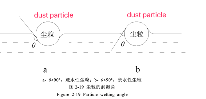
The wettability of dust refers to the degree of affinity between liquid and dust. The affinity of the same dust to different liquids is different; the affinity of different dust to the same liquid is also different. The wettability of dust is related to the type, particle size, shape, generation conditions, components, temperature, moisture content, surface roughness and chargeability of the dust, and is also related to the surface tension of the liquid and the viscosity between the dust particles and the liquid. Adhesion is related to contact mode [31]. The degree to which a liquid wets a solid surface depends on the force exerted by the liquid molecules on the solid surface molecules. The size of wettability is often expressed by wetting angle. The wetting angle means that when solid particles are immersed in the liquid, the surface tension of the liquid acts on the tangent of the solid-liquid contact point, and the angle θ between the tangent and the surface of the dust particle is called the wetting angle. For hydrophobic dust particles, the liquid shrinks on the dust particle surface, θ>90°, as shown in Figure 2-19a; for hydrophilic dust particles,As mentioned above, the height of the throttle baffle directly affects the size of the inertial increment after the airflow passes through the baffle. The smaller the size, the less water droplets will leave the liquid surface, and the larger the particle size, the worse the condition of the water curtain in the mixing chamber, and the lower the dust removal efficiency; on the contrary, the lower the baffle height, the greater the energy obtained by the liquid surface. The better the condition of the water curtain in the mixing chamber, the higher the dust removal efficiency; however, if the height of the baffle is too low, the particle size of the water droplets will be too small, and the dust will be discharged from the outlet with the airflow bypassing the water barrier, thereby reducing the dust removal efficiency. . Therefore, there must be an optimal throttle baffle height hm, so that the dust removal efficiency of the dust collector at a certain frequency can reach the highest.
Take the f=50Hz curve in Figure 2-18 as an example, the curve as a whole shows a trend of rising first and then falling, and reaches the maximum value at h=50mm, that is to say, when the operating frequency of the induced draft fan is 50Hz, the optimal throttle gear Board height hm=50mm. At this time, reducing the height of the baffle will lead to severe water discharge at the outlet of the dust collector, and the dust removal efficiency will decrease; if the height of the baffle is increased, the inertia increment will decrease after the airflow bypasses the baffle, and the condition of the water curtain in the mixing chamber will deteriorate, reducing the dust removal efficiency. For the two cases of frequency f=25 and 30Hz, there is only a descending section in Fig. 2-18. This is because the initial inertia of the airflow in these two cases is too small, so under this test condition, there is no water droplet size that is too small. In the case of severe water discharge at the outlet, the hm at these two frequencies should be less than or equal to 30mm.
The aroused water droplets break away from the air flow line in the mixing chamber and collide with the water film formed on the deflector, which also has a trapping effect on the dust particles. The capture effect of water film on dust is very complex, and its capture efficiency is related to factors such as dust particle size, dust concentration, wettability of dust, and stability of water film.
The larger the particle size of the dust, the greater the degree of separation from the streamline when the airflow encounters the deflector and the deflection of the streamline, so the greater the probability of hitting the water film and being captured. In addition, the dust is captured by the liquid film. In fact, the gas-solid interface on the outer wall of the dust particle is replaced by the liquid-solid interface, and the dust particle breaking through the outer gas film is the prerequisite for this replacement. The particles are not easy to break through because they are tightly wrapped by the air film, and it is difficult to be captured by the water film.
Excessive dust particle concentration will reduce the dust removal efficiency of the water film. Excessive particle concentration may cause the dust particles that escape from the air flow line and hit the water film to collide with the dust particles suspended in the water film and be bounced back into the air flow.
The stability of the water film mainly refers to the stability of the thickness of the water film. If the thickness of the water film is too small, it will be pulled into small water droplets by the airflow, which will obviously reduce the collection efficiency of dust particles. The water film on the deflector of the shock-type water curtain dust collector is definitely not stable compared with the general water film dust collector, but due to the large amount of water droplets being excited in the mixing chamber, it can ensure that the water film on the deflector is stable. A certain thickness of the water film.
Based on the wetting angle, it is judged whether the dust particles are captured in the water film dust removal. In the research, it is assumed that the dust particles are captured when they are immersed in the liquid, and the calculation formula of the wetting angle at this time is obtained:
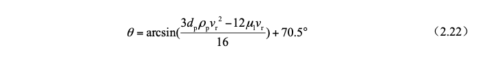
μl—Dynamic viscosity coefficient of water,(Pa·s);
vr—The velocity of dust particles in the vertical direction of the water film,m/s。
The wetting angle of dust particles in the actual environment is recorded asθ',if θ'<θ,Dust particles can be immersed in the water film to reach or exceed ’s deep,thereby being captured;if θ'>θ,The ability of the water film to capture dust particles is reduced.
2.3 Force and Motion Analysis of dust particles
The flow field area in the mixing chamber of the self-initated water curtain dust collector is a gas-liquid-solid three-phase flow, the gas is the continuous phase, and the liquid droplets and dust particles are the dispersed phase. Dust particles interact with gas, liquid droplets and other particles in this three-phase flow, and the stress conditions are very complicated. However, since the interaction between particles and gas plays a dominant role in particle motion, only Briefly analyze the force condition of a single dust particle in the gas.
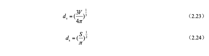
The shapes of dust particles in the airflow are various, and it is most convenient to use spherical particles when analyzing the force on the particles. Therefore, the concept of "equivalent diameter" is introduced for the calculation of irregular particles. The stress situation is the same as that of spherical particles with equivalent diameter. The equivalent diameter is divided into volume equivalent diameter dv and surface area equivalent diameter ds, which are defined as follows:The flow field area in the mixing chamber of the self-initated water curtain dust collector is a gas-liquid-solid three-phase flow, the gas is the continuous phase, and the liquid droplets and dust particles are the dispersed phase. Dust particles interact with gas, liquid droplets and other particles in this three-phase flow, and the stress conditions are very complicated. However, since the interaction between particles and gas plays a dominant role in particle motion, only Briefly analyze the force condition of a single dust particle in the gas.
The shapes of dust particles in the airflow are various, and it is most convenient to use spherical particles when analyzing the force on the particles. Therefore, the concept of "equivalent diameter" is introduced for the calculation of irregular particles. The stress situation is the same as that of spherical particles with equivalent diameter. The equivalent diameter is divided into volume equivalent diameter dv and surface area equivalent diameter ds, which are defined as follows:
1)Drag resistance FD
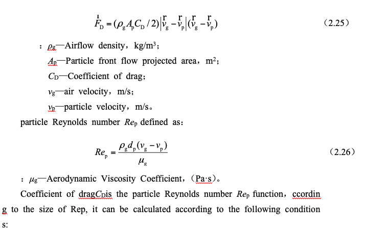
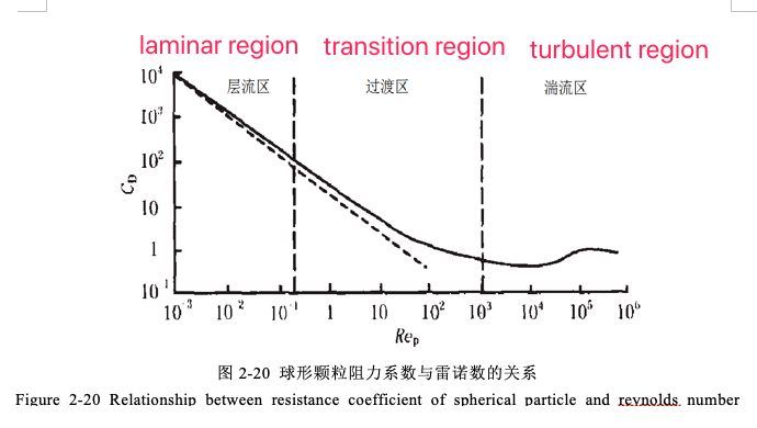
laminar flow zone(Stokes区):10-4<Rep<0.3,CD=24/Rep
Transition zone(Allen区):0.3<Rep<500,CD=10/(Rep)1/2
Turbulent zone(Newton区):500<Rep<103,CD=0.44
The relationship curve between the two is shown in Figure 2-20
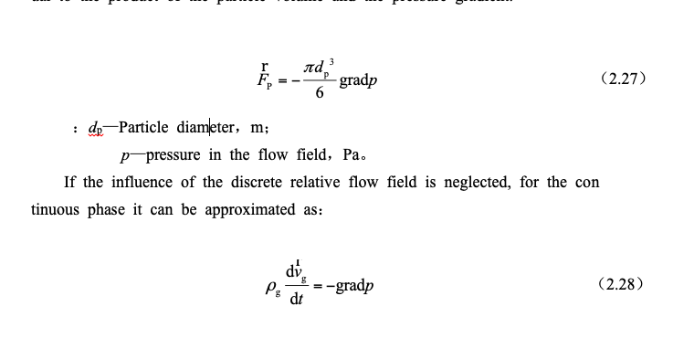
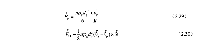
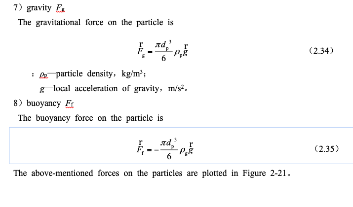
2)pressure gradient force FP
In a flow with a pressure gradient, particles will always be affected by a resultant force that is not zero. This resultant force is the pressure gradient force. FP is opposite to the direction of the pressure gradient, and its size is equal to the product of the particle volume and the pressure gradient.
3)Magnus Force FM
The dust particles in the airflow are due to the vorticity of the airflow and the collision with other particles or walls
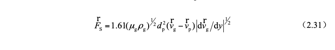
4)Saffman Force FS
In addition to the rotation of the particle itself will generate a force perpendicular to the direction of motion, the existence of the velocity gradient in the flow field makes the flow velocity on both sides of the particle different, and will also generate a force from the low-speed side to the high-speed side,即Saffman force,It is the result of the combined action of slip (relative motion) and shear, and its direction always points to the high-speed side, that is, the center of the flow field, so it is also called slip-shear lift.
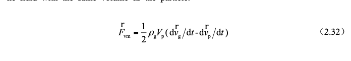
5)additional mass force Fvm
When the particle moves at a variable speed in the airflow, it will drive the surrounding fluid to move at a variable speed, which requires the particle to exert a force on the surrounding fluid. According to Newton's third law, the surrounding fluid must also have a reaction force on the particle. This The force is called the added mass force. The additional mass is half the mass of the fluid with the same volume as the particle.
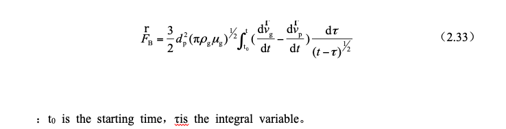
6)Basset forceFB
When the particle is moving at a variable speed, in addition to the additional mass force of the surrounding fluid, it will also receive an additional resistance. This is due to the fact that the fluid layer attached to the particle will generate fluidity and viscosity when it is moving at a variable speed. deformation. This time-varying fluid force due to the instability of the fluid layer on the particle surface is called the Basset force.

At this time, the particles decelerate in the vertical direction, and the resulting force is
Although the forces acting on particles are quite complicated, not all forces are equally important in general. Many scholars have studied and calculated the forces on particles in airflow, but due to different experimental conditions, it is concluded that The results vary. In most areas of the flow field, the Magnus force is at least an order of magnitude smaller than the Saffman force and drag resistance, and for mineral powder particles, the Basset force can also be ignored. it concluded that when the rotation speed of pulverized coal particles is 1800 rpm, the Magnus force is about 1% of the drag resistance. Cen Kefa came to the following conclusion: Under various conditions of pulverized coal particles, the order of magnitude of additional mass force, pressure gradient force, and Saffman force is very small and generally negligible, but in the boundary layer, due to The velocity gradient is very large, so the Saffman force cannot be ignored at this time; the magnitude of the Magnus force is equal to the gravity at each particle size, which plays a role in balancing gravity; in turbulent flow motion, Basset force is a very important force; drag resistance It is the maximum force acting on the pulverized coal particles, which plays the role of accelerating the particles.
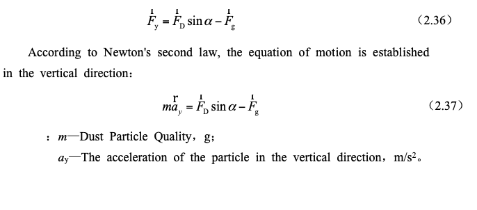
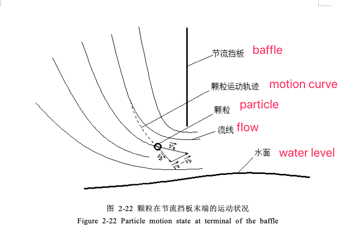
The following discusses the movement state of dust particles with the dust-laden airflow around the end of the throttling baffle. According to the conclusions of the above-mentioned scholars, only the drag resistance FD and gravity Fg are considered here.
When the dust-laden airflow passes through the throttling baffle, the airflow streamline is compressed and the direction changes sharply. The particles that originally moved along the streamline direction gradually depart from the original streamline, and then intersect with other airflow streamlines. At this time, the velocity of the particles and the airflow It is no longer in the same direction, as shown in Figure 2-22, so the direction of its drag resistance also changes, as shown in Figure 2-23.At this time, the particles decelerate in the vertical direction, and the resulting force is
Although the forces acting on particles are quite complicated, not all forces are equally important in general. Many scholars have studied and calculated the forces on particles in airflow, but due to different experimental conditions, it is concluded that The results vary. In most areas of the flow field, the Magnus force is at least an order of magnitude smaller than the Saffman force and drag resistance, and for mineral powder particles, the Basset force can also be ignored. Literature [43] concluded that when the rotation speed of pulverized coal particles is 1800 rpm, the Magnus force is about 1% of the drag resistance. Cen Kefa came to the following conclusion in literature [44]: Under various conditions of pulverized coal particles, the order of magnitude of additional mass force, pressure gradient force, and Saffman force is very small and generally negligible, but in the boundary layer, due to The velocity gradient is very large, so the Saffman force cannot be ignored at this time; the magnitude of the Magnus force is equal to the gravity at each particle size, which plays a role in balancing gravity; in turbulent flow motion, Basset force is a very important force; drag resistance It is the maximum force acting on the pulverized coal particles, which plays the role of accelerating the particles.
The following discusses the movement state of dust particles with the dust-laden airflow around the end of the throttling baffle. According to the conclusions of the above-mentioned scholars, only the drag resistance FD and gravity Fg are considered here.
When the dust-laden airflow passes through the throttling baffle, the airflow streamline is compressed and the direction changes sharply. The particles that originally moved along the streamline direction gradually depart from the original streamline, and then intersect with other airflow streamlines. At this time, the velocity of the particles and the airflow It is no longer in the same direction, as shown in Figure 2-22, so the direction of its drag resistance also changes, as shown in Figure 2-23.
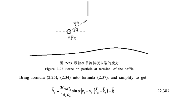
From the analysis of the comprehensive formula (2.38) and section 2.2.2, it can be obtained that with the increase of the particle diameter dp, the inertial energy of the particle in the vertical direction will be greater, and the acceleration of deceleration motion in this direction will decrease. To obtain vertical upward velocity with the airflow into the mixing chamber requires a greater vertical distance, and the distance between the end of the baffle and the water surface is almost constant, so the particles fall into the water below more easily.
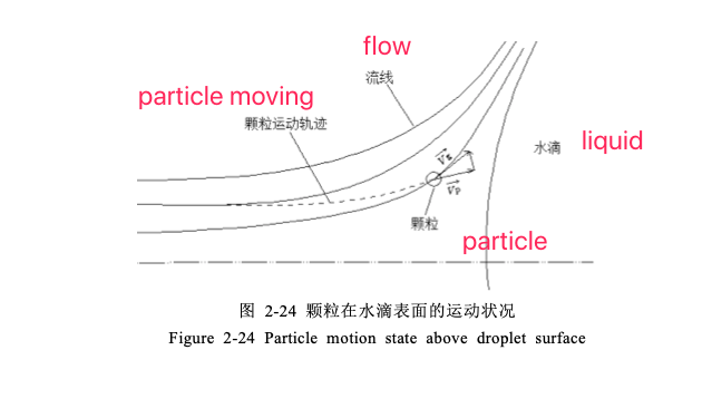
In the mixing chamber, the movement of dust particles in the airflow near the surface of the water droplet is shown in Figure 2-24. After analysis by the above method, the same conclusion is reached, that is, the larger the particle size, the easier it is to break away from the streamline and hit the surface of the water droplet to be trapped.2